| Author | Message | ||
| Tim James (Tjames)
Registered Member Username: Tjames Post Number: 13 Registered: 8-2006 Posted From: 66.59.117.23 Rating: N/A |
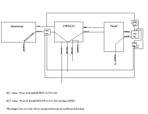
Hi everyone...I'm attaching a diagram of my proposed electric hook-up. I'd appreciate feedback. I think I have it all figured out, but it never hurts to have others look at it. Especially those who know more than I do. Thanks, Tim  | ||
| Jerry Liebler (Jerry_liebler)
Registered Member Username: Jerry_liebler Post Number: 239 Registered: 3-2005 Posted From: 75.89.155.47 Rating: N/A |
Tim, The print is too fine to clearly see. I see at least one problem if the shore cord is plugged in and the shore breaker is open you will have 2 ground to neutral bonds, one at the shore power source and another either on the inverter output or the generator. Also the relay in the generator neutral needs a contact rating at least as great as the generator's output current. Also, I believe your design would have 2 ground neutral bonds if the shore cord was plugged in and the generator is running. I believe I solved these problems with a design that uses N.O. contactors in both the generator and shore inputs(both nutral and hot) and a heavy N. C. relay that connects the ground and neutral unless either generator or shore power is present and a 4P.D.T. relay that controls which contactor is allowed to operate and chooses the power source for the ground neutral de-bonding relay. Since the 4P.D.T. is wired to provide generator priority, the generator autostart works to allow the generator to recharge the battery even when a shore cord that's too small for the load is being used. | ||
| George M. Todd (George_mc6)
Registered Member Username: George_mc6 Post Number: 51 Registered: 8-2006 Posted From: 207.231.81.154 Rating: N/A |
Tim, Please expand the print so us old goats can read it. However, YOU CAN'T HAVE GROUNDS AND NEUTRALS TOGETHER ANYWHERE IN A BUS!!! There is a month-old post concerning wiring, and somebody suggested explaining why no grounds and neutrals together. The answer is electrocution, as mentioned by several of us then, and there will be a bunch of posts behind mine, as soon as a bunch of us notice! Wire the panel as a "sub-panel," with the grounds on one bus bar bonded to the panel, the generator ground, the inverter ground, and the bus frame. Wire the neutrals to THE INSULATED BUS BAR. Remove the green neutral to ground screw or jumper in the panel. Don't attempt to switch the grounds anywhere. A ground to neutral bond, plus a mis-wired campground, equals the whole bus being energized. The bus will also become energized if a contact fails anywhere in the neutral circuit. You become the ground path when you open the door from the lawn, or connect your water hose! A suggestion is to use a double-pole, double-throw relay in the shore/generator circuit. Connect the shore to the normally closed side, and the generator to the normally open side, and the common to the inverter. Use a relay with a 120V coil, connect the coil to the generator output, through a 4 or 5 amp fuse, and the normally closed contacts of a two pole push button. The normally open button contacts stop your generator. This circuit keeps your A/C compressors from following the generator as it slows down. (I learned that from experience.) If you can't find a high amperage double throw relay, use two single throws, and add an auxiliary contact to each, with the coil of one connected through the normally closed aux. of the other. This protects the gen from shore power. Good luck, hope I didn't scare you, but we do want you and yours to enjoy this Christmas, and many more. HH, George |