| Author | Message | ||
| Roger Baughman (Roger)
Registered Member Username: Roger Post Number: 74 Registered: 11-2006 Posted From: 69.232.72.24  Rating: N/A |
I want to install a 50 amp outlet at my home to plug in my MCI while at home. Can someone tell me how to hook up the four wires? I saw the the tread on how someone made an adapter to plug ito a dryer outlet and how dangerious it is. I want to do it so as not to energize my bus frame. Thanks, Roger | ||
| Luvrbus (Luvrbus)
Registered Member Username: Luvrbus Post Number: 670 Registered: 8-2006 Posted From: 74.32.92.133 Rating: N/A |
Roger, I bought the 50amp shore power plug for RV's in a enclosed box for 35 bucks at an electrical supply good luck | ||
| Bob Baldwin (Bob4106)
Registered Member Username: Bob4106 Post Number: 167 Registered: 10-2004 Posted From: 24.74.180.20  Rating: N/A |
maybe this will help. 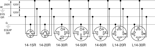 | ||
| Sean Welsh (Sean)
Registered Member Username: Sean Post Number: 789 Registered: 1-2003 Posted From: 67.142.130.44 Rating: |
Roger, The receptacle you want is a NEMA 14-50R, which you will find in home improvement stores, normally labeled as a "range" receptacle. On the back side of this, where the wires connect, you should find either markings or color-coded screws to assist you in connecting the wires. The Ground terminal should have a green screw, sometimes with a hex head, or be marked "G". The Neutral terminal will have a silver screw, and/or be marked "N" or "W". The two hot terminals will have brass colored screws and/or be marked "R" and "B" OR "X" and "Y". To double-check yourself, look at the front. The round or U-shaped opening is the ground, and the slot diametrically across from it is the neutral. The other two slots are the hots. Make sure you use 6-gauge wire for the hots and neutral; 8-gauge is permitted for the ground. Hope this helps. -Sean http://OurOdyssey.BlogSpot.com | ||
| Roger Baughman (Roger)
Registered Member Username: Roger Post Number: 75 Registered: 11-2006 Posted From: 69.232.72.24 Rating: N/A |
Bob, Is the second line down on your diagram marked (W) the nutrel bar in the house electrical cabinet? And is the lower line marked equip GR, the ground that goes to the ipe in the dirt for the house? Thanks, Roger | ||
| Sean Welsh (Sean)
Registered Member Username: Sean Post Number: 790 Registered: 1-2003 Posted From: 67.142.130.44 Rating: N/A |
Roger, In your main electrical panel (where the branch circuit breakers are located) you should have both Ground and Neutral buss-bars. If this is the only electrical panel in your house, and is the main point of entry for your electrical service, it is possible that these bars may be tied together. The green (or bare) grounding wire goes from the G terminal on the outlet to the ground buss-bar, the white neutral wire goes from the W terminal on the outlet to the neutral buss-bar. -Sean http://OurOdyssey.BlogSpot.com | ||
| Roger Baughman (Roger)
Registered Member Username: Roger Post Number: 76 Registered: 11-2006 Posted From: 69.232.72.24 Rating: N/A |
Thanks Sean, I appreciate it very much, Roger | ||
| Buswarrior (Buswarrior)
Registered Member Username: Buswarrior Post Number: 1516 Registered: 12-2000 Posted From: 76.68.134.110  Rating: N/A |
Something to watch for in the quest to build a 50 amp system... There are many of these 50 amp replacement male power plugs with a lead available at the big box store that have a smaller gauge wire on the neutral. No problem when on the 240 volt, but pigtail down to 120, or a site wired same phase on both hots... May not be a good thing when everything goes back via the neutral. happy coaching! buswarrior | ||
| Sean Welsh (Sean)
Registered Member Username: Sean Post Number: 791 Registered: 1-2003 Posted From: 67.142.130.44 Rating: N/A |
Buswarrior, Not really relevant to the OP topic (he's looking for the other end -- the receptacle to wire to the house), but the type of cord you are talking about is a "Range cord." Generally, these are a maximum of 6' in length, with a molded 14-50P plug on one end, and loose wires with crimped-on ring terminals on the other, along with a strain-relief device for the cord. Often, as you note, these cords are "6/2-8/2," meaning they have two 6awg wires for the hots, and 8awg wires for both the neutral and ground. These cords are only approved for use on 240-volt ranges, wherein all the burners are 240-volt elements. The neutral wire on these ranges carries only current from "incidental" items on the range, such as controls, lights, exhaust fans and the like. You are absolutely correct that these should never, ever be used as part of the shore cord assembly on a bus conversion. It is dangerous, not only in the circumstances that you mentioned, but even if the park power is wired correctly. If you should happen to run loads only on one leg of power, you could be drawing up to 50 amps through the neutral wire. While some 8awg conductors in free air are rated to carry this much current, conductors in a manufactured cord assembly are not, and 6awg is required. Listed RV power supply cords are usually 6/4, although some may be 6/3-8/1, where the ground conductor is 8awg. Anyone who is considering building their own shore cable should do likewise. The type of cable you will need is "SO" or "SJ," which are typically found in 6/4 but can be special-ordered in 6/3-8/1. -Sean http://OurOdyssey.BlogSpot.com | ||
| Roger Baughman (Roger)
Registered Member Username: Roger Post Number: 77 Registered: 11-2006 Posted From: 69.232.64.102 Rating: N/A |
Thank you all for your help in hooking up my 50 amp service for my MCI. Here is a picture for your scrutiny. Thanks again, Roger PS I tryed to attach the picture but I got the to big error notice. Tryed to make it smaller but it still didn't work. | ||
| Tim Brandt (Timb)
Registered Member Username: Timb Post Number: 282 Registered: 10-2003 Posted From: 66.165.176.62  Rating: N/A |
Roger if you email me the pic I can host it on my web space for you | ||
| Tim Brandt (Timb)
Registered Member Username: Timb Post Number: 284 Registered: 10-2003 Posted From: 66.165.176.62 Rating: N/A |
Here is Rogers picture. Just click the link http://members.tccoa.com/timb/elec.jpg Tim | ||
| Sean Welsh (Sean)
Registered Member Username: Sean Post Number: 799 Registered: 1-2003 Posted From: 67.142.130.32 Rating: N/A |
Roger, The photo does not cover much, so it's hard to comment on it. [Earlier remark deleted -- see below.] Not shown is the neutral connection, or the other end (with the receptacle). -Sean http://OurOdyssey.BlogSpot.com (Message edited by Sean on March 23, 2009) | ||
| Sean Welsh (Sean)
Registered Member Username: Sean Post Number: 802 Registered: 1-2003 Posted From: 67.142.130.46 Rating: |
Oops. Re-checking this thread, and I need to modify my "looks fine" comment. Sometimes a quick glance can fool even an old hand like me -- the usual red-black-red-black sequence of colors is generally "normal." However, in this case, you seem to have the colors backwards on either the 50-amp or the 30-amp portion of your "quadplex" breaker. This could be a safety hazard to electricians working on the panel or circuits later. Each 1" half of a quadplex ties to a single bar on the load center. So there should be two black wires in one half, and two red wires in the other. Which is which depends on how the rest of the panel is wired, impossible to tell from the small segment shown in the photo. You should reverse the two #6 wires on the 50-amp (center) circuit, or the two #10 wires on the 30-amp (outer) circuit. Again, which one you should do depends on the rest of the panel. -Sean http://OurOdyssey.BlogSpot.com | ||
| R.C.Bishop (Chuckllb)
Registered Member Username: Chuckllb Post Number: 576 Registered: 7-2006 Posted From: 70.212.254.112 Rating: N/A |
Unless he ran out of a particular color and elected to use the other.......  ..in which case, he might want to re-think what he has done. RCB | ||
| Gary Pasternak (Cessna5354)
Registered Member Username: Cessna5354 Post Number: 62 Registered: 2-2007 Posted From: 72.75.143.101 Rating: |
Sean, Never met you, but look forward to the opportunity, as you are "Good". I read this twice, and looked twice, but read into your comment that all the Red conductors shold be derived from the same side of the panel. Having said that, I am not sure that electricians actually do keep the same convention thru out a panelboard. If a two pole breaker is "moved" down one breaker space it would reverse the say, Red side on Right. You have a sharp eye and are extremely safety consious, and an even better technical writer. Have a Great Day. Gary | ||
| Sean Welsh (Sean)
Registered Member Username: Sean Post Number: 804 Registered: 1-2003 Posted From: 72.171.0.141 Rating: |
Gary, Please let me clarify my comment, as I want to be sure there is no confusion about what "half" I am talking about: In a residential-type panel (split-phase service), there are two separate "hot" busses (in commercial panels, which are often three-phase, there would be three hot busses). Typically, the busses run down either side of the vertical center line of the panel, with "fingers" that reach over to the center line. On a panel designed for 1" breakers, such as the Cutler-Hammer model pictured above, each successive 1" space will therefore alternate between the left and right buss-bars. On two-pole circuits, the "standard practice" is to color-code the branch circuit wires the same as the incoming mains. So a black wire will be connected to the pole of the breaker on the black main, and the red wire to the red main. Confusion arises, however, when using so-called "tandem" breakers. These goodies allow you to increase the circuit capacity of the panel by incorporating two half-inch wide breakers into a single 1" wide unit, which fits neatly into the 1" spacing of the panel. Because this tandem breaker attaches to a single tang on a single buss-bar, it will either be on the red main or the black main, and wire colors (where appropriate) should match. The breaker shown above is an uncommon arrangement, consisting of two tandem breakers "ganged" together into a "quad" arrangement. What this gives you is two separate two-pole circuits in a weird arrangement -- one circuit is on the "inner" pair of handles, and the other circuit is on the "outer" pair. The inner pair has a fairly conventional "handle-tie," whereas the outer pair utilizes an interesting plate-style arrangement to effect the handle-tie. Note that, with a quad like this, both "upper" handles are on one main tang, and both "lower" handles are on the other main tang. If the panel was filled strictly with 1" (full-width) breakers, then the colors would alternate from top to bottom, black-red-black-red etc. on the left side, and red-black-red-black etc. on the right side. With some number of "tandem" breakers, the alternating pattern is disrupted, as both wires from a tandem should be the same color. If the panel was filled entirely with tandems, you'd see black-black-red-red etc. on the left side, and red-red-black-black etc. on the right. I should note here that standard practice in the industry is to use black wire exclusively when running single-pole circuits, so, in practice, most panels are full of mostly black wires, regardless of which main buss they connect to, and it is only two-pole circuits where any red wire comes into play. But safe practice dictates that, when red wire is used, it be connected to the red incoming main. In the photo shown, two of the four wires must, therefore, be incorrectly connected. Without more of the panel shown, it is not possible to tell which two should be swapped. Hope that clears things up a bit. -Sean http://OurOdyssey.BlogSpot.com | ||
| Gary Pasternak (Cessna5354)
Registered Member Username: Cessna5354 Post Number: 63 Registered: 2-2007 Posted From: 72.75.143.101 Rating: N/A |
Sean, Thanks for response. I understand what you are conveying, however I do not believe that most electricians maintain the consistency thru a panel board. I do believe that the red-blk convention provides an electrician the notice that these conductors have the potential difference (ie 240 volts diff in a residential app.)and they are kept separate. But once these conductors leave the panel, there is no phaseing requirement keeping red on right as I suggested, provides no benefit. However, in a three phase industrial application, BIG difference. The Brn-Org-Yel (BOY)convention for 480 volts will insure personnel and equipment safety to avoid a phase to phase short with a specific piece of equipment. I appreciate your insight, as without opposing views I nor anyone would learn. Have a Great day where ever you are. Gary P.S. I also respect your days of Facilities Management. | ||
| Gary Pasternak (Cessna5354)
Registered Member Username: Cessna5354 Post Number: 64 Registered: 2-2007 Posted From: 72.75.143.101 Rating: N/A |
I will explore this later in the code book and with several electricians as to requirement vs good practice, and report back later. Again, enjoy. | ||
| George M. Todd (George_mc6)
Registered Member Username: George_mc6 Post Number: 761 Registered: 8-2006 Posted From: 64.55.111.6 Rating: N/A |
Here's my nickel, Let's consider "shared neutral" circuits. These use one neutral and ground, along with the two hot wires, to save space in a panel, and reduce voltage drop. These circuits MUST be wired on opposite hot legs, so that the neutral current is only the unbalanced amount. If the two hots were put on the same leg, the neutral current would be the sum of the legs, instead of the difference, and the neutral would melt. So, how does an electrician prevent a mistake? Watch the colors, and where they go on the breaker terminals. Is it code? No. Is it industry practice? Yes. I do have to post a respectful disagreement. PANELS are only rated at 80% continuous load. CIRCUIT BREAKERS trip at 100% of their rating. (Think on the worn out thread about 2 roof airs on a 30 amp park service, they sure won't run on 24 amps...) Then there's Black-Red-Blue for for 208-240 Volt 3 phase... While we're on colors in panels, how else do you keep track of the stinger leg on a 240 Volt 3 Phase Delta? (208 Single Phase to Neutral...) MAIN panels won't have SEPERATE ground and neutral bus bars, as that is where the ground+neutral bond occurs. SUB-PANELS must have seperate ground and insulated neutral bars. And yes, the main panel in a bus IS wired as a sub-panel! KUTGW, George (Message edited by george_mc6 on March 25, 2009) | ||
| Sean Welsh (Sean)
Registered Member Username: Sean Post Number: 807 Registered: 1-2003 Posted From: 67.142.130.44 Rating: N/A |
Gary, I think you are right, that some electricians, working in existing panels, will not respect the color code (e.g., they will connect red wires to the black main). However, if they are working for me, I insist that they do so. What the code has to say about this is fairly limited. Article 210.5, "Identification for Branch Circuits," paragraph (C) says, in part
So code requires the circuits to be marked by "phase or line" at every point, in a way that is "documented." Most code officials interpret this to mean that multi-wire branch circuit color coding must be consistent among all circuits in the panel and match the panel supply. You are also right that a journeyman electrician would never play fast and loose like this with a three-phase panel (whether the colors are BOY, as you wrote, or Black-Red-Blue which is the standard for 208/120), because, as you know, getting the colors wrong at a three-phase motor will cause the motor to spin backwards, or cause other equipment damage. -Sean http://OurOdyssey.BlogSpot.com | ||
| Sean Welsh (Sean)
Registered Member Username: Sean Post Number: 808 Registered: 1-2003 Posted From: 67.142.130.44 Rating: N/A |
George, I must respectfully disagree with this statement:
This is only true in limited circumstances. Most breakers are designed to trip magnetically (instant trip) at 100% load, and thermally (trips over time) at 80% load over a certain period of time. Back in 1996, the code used this language explicitly in section 384-16. However, the language was deemed confusing, and the requirement was re-written into Article 210 in the 1999 code, where you can still find it today in the 2008 edition. The language now requires OCPD's to be rated for 100% of the "continuous" load (where "continuous" is defined as three hours or more), and 125% of the "non-continuous" load; a little quick math will show that this means the continuous load can be at most 80% of the maximum load. HOWEVER, there is an exception to Article 210-20(a) which states
So, if the terms of the listing for all components allow 100% operation, then the breaker may be permitted to carry 100% of the handle rating continuously. There are some very specific requirements to be followed. This has led to manufacturers now building "100% breakers" and "80% breakers." This publication from Square-D does a good job explaining the difference: http://ecatalog.squared.com/techlib/docdetail.cfm?oid=0900892680055a4e In regards to colors,
you are correct. This is actually a special case under the code, which mandates that the so-called "wild leg" be Orange in color (Article 230.56). -Sean http://OurOdyssey.BlogSpot.com (Message edited by Sean on March 25, 2009) |