| Author | Message | ||
| R.C.Bishop (Chuckllb)
Registered Member Username: Chuckllb Post Number: 1383 Registered: 7-2006 Posted From: 75.211.93.158  Rating: |
Anyone have experience with either of these? Comments, please. Thanx  RCB | ||
| Justin Griffith (Justin25taylor)
Registered Member Username: Justin25taylor Post Number: 59 Registered: 4-2007 Posted From: 68.93.132.49 Rating: N/A |
RCB, I know some folks will disagree, but for me the combiner works great. If I am running the main engine, genset, or shore power it keeps all of my batteries ready to go at all times. The isolator does fine too (if you correct for voltage drop or use one of the new style ones) but you aren't able to charge your start batteries from the inverter/charger unless you use two isolators or a manual switch. I do think one of the companies now makes an isolator that will send power from any bank to any bank. If you are asking about one of these, I have not used one. One Mr Sean should be along to answer your question in better detail. In my mind he has the most well thought out electrical system of any coach I have seen. I know you have been having some battery type problems as of late and if you have some free time to call, I'd love to ask you some questions and give you my thoughts. My number is in my profile. Best, Justin | ||
| Sean Welsh (Sean)
Registered Member Username: Sean Post Number: 1161 Registered: 1-2003 Posted From: 199.90.92.4  Rating: N/A |
Chuck, I had a Xantrex Pathmaker, which is theoretically a "smart" combiner. My experience is that it tried to be too smart, and I was not happy with the decisions it made, particularly about disconnecting under certain circumstances. Also, it is bi-directional and there is no way to defeat that, and I don't really want the flooded start batteries to be in the picture when the fancy three-stage charger is charging the expensive deep cycle AGMs. I ultimately ditched it for the tried-and-true method of a solenoid driven by the alternator relay terminal. I added a time delay so that the house batteries do not get brought in while the engine is still cranking. I don't care for isolators. They waste a lot of power as heat, and there is always the dilemma of which side to put the sense lead on. Whichever side you pick, the other bank is likely to get either over- or under-charged. Just my $0.02. -Sean http://OurOdyssey.BlogSpot.com | ||
| R.C.Bishop (Chuckllb)
Registered Member Username: Chuckllb Post Number: 1385 Registered: 7-2006 Posted From: 75.211.150.68 Rating: N/A |
Thanx, much Justin and Sean..... Sean... would you send me.... or post here...a sketch of your solenoid alternator relay plus the time delay? I, like you, do not care for Isolators...as I know them...just don't "trust" them to do as I need....keeping both banks charged while traveling. By the time we get to a destination, fridge and other draw downs have pretty well "done in" the house bank. Then, of course, it is the genset for a couple to three hours. Understand the "smart" isolator is a different breed. Justin...what combiner do you have? Thanx, RCB | ||
| Justin Griffith (Justin25taylor)
Registered Member Username: Justin25taylor Post Number: 60 Registered: 4-2007 Posted From: 67.67.217.146 Rating: N/A |
Xantrex Pathmaker. Keep in mind I do not have the AGM batteries as Sean does. My start batteries are 3- group 31 lead acid, and my house bank consists of 6- 6 volt Trojan Golf cart batteries. The battery on my generator is a plain lead-acid variety and is not hooked to the pathmaker. I use the generator enough to keep the battery charged and I have a manual switch between it and the start batteries "just in case" I need to jump it from the main start bank. I use the 50DN for charging on the road and a stand alone 50 amp 3 stage marine charger for the generator and power pole. Best, Justin | ||
| Jim Wilkerson (Wagwar)
Registered Member Username: Wagwar Post Number: 103 Registered: 12-2009 Posted From: 99.109.187.242 Rating: N/A |
Hi, I'm not trying to hijack this thread, but could someone explain in more detail the cons of using a battery isolator for keeping the house batts charged off the engine alt? I have a Wrico International 300AMP Battery Isolator. It must generate some heat, because it has large heat fins radiating out in all directions. Thanks | ||
| Sean Welsh (Sean)
Registered Member Username: Sean Post Number: 1162 Registered: 1-2003 Posted From: 199.90.92.4 Rating: N/A |
"Sean... would you send me.... or post here...a sketch of your solenoid alternator relay plus the time delay?" Chuck, I don't have a sketch, and neither would I suggest my circuit for anyone else. I ended up re-wiring the Pathmaker to just use its internal 12-volt solenoid, and used a fancy 12-volt delay timer that I had lying around. These are about $60 if you have to buy them. I suggest instead that you take the relay signal in as a 24-volt signal from the old coach blower circuit, which should be driven off the alternator's Relay signal. You can build a simple and cheap delay by using some resistance and capacitance; Google "capacitor delay circuit" and you will find many easy-to-build simple circuits that will suffice. Alternatively, 12- and 24-volt fixed delay timers are relatively inexpensive and can be found at Neward, Allied, Del City, and others. I added an on-off-on SPDT switch to my circuit so that I could force the solenoid to connect for emergency starting or to charge coach batteries from the house charger, or force it to disconnect for hill climbing and so forth. If I had a decent drawing program I would try to ship something up for you; in the meantime, give me another shout if any of that is unclear. "could someone explain in more detail the cons of using a battery isolator for keeping the house batts charged off the engine alt?" 1. With an isolator, if you need to bridge the two banks together, say for emergency starting purposes, you'll need to use a switch, solenoid, or jumper cables downstream of the isolator. If you use a solenoid for this, your paying for (and installing) a device that could have done the whole job had it just been wired the right way. 2. The alternator's regulator adjusts the alternator output based on sensing battery voltage right at the batteries. With an isolator, you need to pick which set of batteries will have the sense lead connected. The other bank gets "pot luck" on charge voltage. This means whichever bank is not sensed might get undercharged or even overcharged. 3. When the batteries are depleted, the alternator will be operating at maximum output. The inherent loss in the isolator means that and extra 5% of your alternator output is being wasted as heat in the isolator -- what those big fins are for. With a solenoid or switch, that energy goes into the batteries instead. 4. With an isolator instead of a solenoid or switch, there is no way to disconnect the house load from the alternator, say in order to get back that ten horsepower for hill climbing or whatever. Unless, of course, you also install a switch for that purpose, but then see my comment at #1. On the plus side, there are no moving parts, the wiring is arguably simpler, and you can't accidentally leave the switch in an incorrect position (in the case of solenoid installations with over-ride switches). There will be no flow of energy from one bank to the other for any reason. -Sean http://OurOdyssey.BlogSpot.com | ||
| Jim Wilkerson (Wagwar)
Registered Member Username: Wagwar Post Number: 104 Registered: 12-2009 Posted From: 99.109.187.242 Rating: N/A |
Thank you, Sean! Excellent, thorough, clear and concise! Wow! | ||
| Jim Wilkerson (Wagwar)
Registered Member Username: Wagwar Post Number: 105 Registered: 12-2009 Posted From: 99.109.187.242 Rating: N/A |
Sean wrote: "2. The alternator's regulator adjusts the alternator output based on sensing battery voltage right at the batteries. With an isolator, you need to pick which set of batteries will have the sense lead connected. The other bank gets "pot luck" on charge voltage. This means whichever bank is not sensed might get undercharged or even overcharged." There must be more to this picture that I'm missing. It seems to me that #2 above would still be a problem even with a solenoid and delay timer. Won't the alternator output still be based on the bank being 'sensed'? Thanks. | ||
| R.C.Bishop (Chuckllb)
Registered Member Username: Chuckllb Post Number: 1386 Registered: 7-2006 Posted From: 75.211.5.201 Rating: N/A |
Matter of fact...I'm no E-Guru...but wondered the same... ...Sean?... RCB | ||
| R.C.Bishop (Chuckllb)
Registered Member Username: Chuckllb Post Number: 1387 Registered: 7-2006 Posted From: 75.211.5.201 Rating: N/A |
Here is my situation...briefly, I hope. I am quite sure I am not the only one who experiences this: To begin, let me state I am not new to the "hobby". I have just (last month) purchased all new batteries- Group31 Starts(3)and Golf Cart 6V(5)for House....(due to consideration of size of tray available) I have retained most of the original 12 volt inside lighting (sides, dome,plus a circuit for water pump and shower discharge). Reason= In case of complete shutdown of house system, we can still "function"....Get the idea? These are all off the start system and consequently, use power while sitting for six days (or however many one "sits"). The house system is not presently "charged" as we drive. Therefore, refrigerator, and other appliances draw down as the day progresses, without being replenished. This past week we arrived in the mountains and were, as it were, behind the charge grid when we arrived (160 miles one way). Charged the house thru the genset for a couple of hours (which I hope to eliminate), then into the evening, used TV, etc, etc.. Bottom line, overnight house was drained big time...second night, even after charging for several hours, bottom dropped out of the house batteries. There has to be a better way!!!, Both systems need to be charged when engine is running! AND both systems need to be charged while generator is running. Simple, one should think! All's well that ends well, but what a pain!... RCB | ||
| Sean Welsh (Sean)
Registered Member Username: Sean Post Number: 1163 Registered: 1-2003 Posted From: 67.142.130.13 Rating: N/A |
"It seems to me that #2 above would still be a problem even with a solenoid and delay timer. Won't the alternator output still be based on the bank being 'sensed'?" When the solenoid closes, the two banks are connected together in parallel and now look to the regulator like a single larger bank. Yes, the sense lead will be at one end or the other of the cross-connect cable, and so there might be a small fraction of a volt difference from the reading at the other end of the cable, but this effect is negligible. The SOC of the two banks before combining might be very different, but the alternator is now seeing a combined reading and will be providing charge appropriate for the combined SOC of the larger bank. Remember, with the solenoid closed, the two banks will equalize to the combined SOC even if the alternator is not charging at all. The behavior of this larger combined bank, BTW, will mask the true internal SOC of either bank independently, and this can throw off the setpoints for a more sophisticated charger such as the three-stage chargers found in many inverter/chargers. This is the reason I advise against combining the banks when charging from this source. You will maximize the longevity of your expensive house batteries by charging them independently on a three-stage charger. The alternator and its regulator, however, have but a single setpoint and there is no opportunity for it to get confused, so it is much less of a problem to charge the banks together from the alternator. "Both systems need to be charged when engine is running! AND both systems need to be charged while generator is running." Per my comment above, charging both battery banks from the same three-stage charger is not recommended. So if you really want both systems to charge on the generator, get a second charger for the chassis batteries. A standard automotive trickle-type charger should be sufficient to keep the chassis batteries topped up whenever the genny is running. -Sean http://OurOdyssey.BlogSpot.com | ||
| Jim Wilkerson (Wagwar)
Registered Member Username: Wagwar Post Number: 106 Registered: 12-2009 Posted From: 99.109.187.242 Rating: N/A |
Thank you Sean. On street rods, I used Battery Disconnect Solenoids to allow me to disconnect the batteries with a pressure switch or toggle. Often the batteries were in very inconvenient places and disconnecting the batts was difficult. Could I use one of these to perform this action? Would the solenoid have to be for 24v or would a 12V work? Thanks. | ||
| R.C.Bishop (Chuckllb)
Registered Member Username: Chuckllb Post Number: 1388 Registered: 7-2006 Posted From: 75.211.222.166 Rating: N/A |
Allow me another question: Is there a reason why one should/could not run a separate charge cable from the alternator to the house batteries (as well as simultaneously charging the start batteries while engine is running)...thus eliminating an isolator? Alternator is pretty large. RCB | ||
| Sean Welsh (Sean)
Registered Member Username: Sean Post Number: 1164 Registered: 1-2003 Posted From: 67.142.130.13 Rating: N/A |
"I used Battery Disconnect Solenoids ... Could I use one of these to perform this action?" How the solenoid is marketed is unimportant so long as it has the proper ratings. You want a solenoid rated to "make" and "break" at least 200 amps. As far as voltage, the solenoid does not distinguish between 12 and 24 on the contact side (where the current flows through). However, the coil voltage must be correct for the application. If the signal you are using to drive the solenoid is 24 volts, you need a model with a 24 volt coil. I recommend a White-Rodgers 586-105111 (12v) or 586-114111 (24v), available from Grainger and many other retailers. -Sean http://OurOdyssey.BlogSpot.com (Message edited by Sean on September 10, 2010) (Message edited by Sean on September 10, 2010) | ||
| Bruce Henderson (Oonrahnjay)
Registered Member Username: Oonrahnjay Post Number: 588 Registered: 8-2004 Posted From: 70.61.105.213  Rating: N/A |
RC asked "Is there a reason why one should/could not run a separate charge cable from the alternator to the house batteries (as well as simultaneously charging the start batteries while engine is running)...thus eliminating an isolator?" RC, generally (and if the alternator has an internal regulator) what you're talking about is a "parallel" system. It's not a good idea because if you have a big house battery package that needs a strong charge and a smaller start battery (or battery set) that needs a lesser charge, the regulator will "see" the big battery set needing the big charge. It will also send that "big strong charge" to start batteries, resulting in overcharging and damage to the batteries. (Again, there are a hundred detail differences that might impact this but generally, that's how it works.) | ||
| Sean Welsh (Sean)
Registered Member Username: Sean Post Number: 1165 Registered: 1-2003 Posted From: 67.142.130.13 Rating: N/A |
"Is there a reason why one should/could not run a separate charge cable from the alternator to the house batteries (as well as simultaneously charging the start batteries while engine is running)...thus eliminating an isolator?" An isolator ensures that the current flows in only one direction: from the alternator to the batteries. Merely running another cable from the alternator output post to a second set of batteries is no different from connecting the battery banks together directly at their positive terminals -- current will flow in both directions via the post on the alternator. What you would have is one single large bank, not separate banks for house and chassis. Is that what you want? No harm in having just one bank, but why complicate it by putting some of the batteries in one place and some in another, then using the alternator as a terminal bock to tie them together? -Sean http://OurOdyssey.BlogSpot.com | ||
| Sean Welsh (Sean)
Registered Member Username: Sean Post Number: 1166 Registered: 1-2003 Posted From: 67.142.130.13 Rating: N/A |
"RC, generally (and if the alternator has an internal regulator) what you're talking about is a "parallel" system. It's not a good idea because if you have a big house battery package that needs a strong charge and a smaller start battery (or battery set) that needs a lesser charge, the regulator will "see" the big battery set needing the big charge. It will also send that "big strong charge" to start batteries, resulting in overcharging and damage to the batteries." Umm, actually, not true if there is no isolator, which was the question. Without an isolator, the regulator will see the batteries as one large bank and will charge accordingly. After a period of just a few days, the bank will be completely equalized, assuming all batteries are the same type. The problem you mention is precisely the one caused by isolators, which I mentioned several posts ago. And you can't use an isolator at all with an internally regulated ("one-wire") alternator. -Sean http:\OurOdyssey.BlogSpot.com | ||
| R.C.Bishop (Chuckllb)
Registered Member Username: Chuckllb Post Number: 1389 Registered: 7-2006 Posted From: 75.211.222.166 Rating: N/A |
Yep....and in my "in depth" thinking about this...(sure!) , I over looked the obvious! I have actually done this in the past, but elected not to do it again for reasons stated. So I am left with the same question (statement): There has to be a better way!!!, Both systems need to be charged when engine is running! AND both systems need to be charged while generator is running. Is there a device available which would allow charging from the alternator....(simultaneously)..then on to the house batteries? What am I not seeing clearly?...I have pretty well beat myself up on this. BUT, be assured, I WILL find something (reasonable) that will do the job!! I have no room to mount a second alternator........ This appears to do what I want when using the inverter, but doesn't take care of charging (without using the generator) while engine is running...or maybe two would need to be used??? Good grief! http://www.goldduo.com/electrical-batt-isolators-c-1651_3212_3213/newmar-newmar-bi-100-12v-battery-integrator-p-1293405 RCB (Message edited by Chuckllb on September 10, 2010) | ||
| Sean Welsh (Sean)
Registered Member Username: Sean Post Number: 1167 Registered: 1-2003 Posted From: 67.142.130.13 Rating: N/A |
Chuck, That device is essentially identical to the Pathmaker that I mentioned way up top. Internally it is nothing more than a solenoid with a small circuit board that is monitoring the voltage on both sides. It will work, but again I advise against combining the banks when using the shore or generator powered charger. A plain solenoid hooked to either an oil pressure switch or the Relay terminal is much cheaper and gets the job done. If you really need to charge the chassis batteries when the genny is running, get a cheap trickle charger and plug it in to a generator circuit. -Sean http://OurOdyssey.BlogSpot.com | ||
| Don Evans (Doninwa)
Registered Member Username: Doninwa Post Number: 281 Registered: 1-2007 Posted From: 208.81.157.234  Rating: N/A |
RCB, You say five 6 volt batteries in your house system? Must be a typo. Sounds to me like the simplest system to do what you want is a solenoid, since you don't like isolators, to charge both banks from the engine. Well, simplest might be a manual switch, as long as you don't forget it. There are chargers that will charge multiple banks from an AC source, generator or power pole. You could also have two separate chargers, one for each bank. Smart or multi-stage charger are the way to go. You would probably want chargers that are fairly high output to minimize generator run time. Chargers must be designed to be continuously connected to batteries to avoid draining them when not connected to AC. Good luck Don 4107 | ||
| R.C.Bishop (Chuckllb)
Registered Member Username: Chuckllb Post Number: 1390 Registered: 7-2006 Posted From: 75.211.222.166 Rating: N/A |
Well, Sean...once again I perfectly (I think) understand your English...but you lose me (remember I am and E dummy)when you talk about about "hook to an oil pressure switch or the Relay terminal...am willing to do that, but...just don't have the "expertise" to follow thru with "just" english...  . NEED A schematic! . NEED A schematic! So I am guessing that the Trickle charger you talk about would be 10 amps or so, plug into Generator/Shore outlet...after the transfer switch..., connect to batteries?? And just how long would that trickle charger take to bring those starts back to 12.6? My solar panels (20 watts total) won't do it in the trees. Don...you are correct SIX is the correct number of batteries...parallel/series 12 volts. Once again, not sure how the solenoid "works" in the picture. Just not sophisticated enuf to "see the picture"...but I do know how to read drawings... Thanx, fellows...UR the Best!!! What a great bunch!!!... and thanx Ian!! U2! RCB | ||
| Don Evans (Doninwa)
Registered Member Username: Doninwa Post Number: 282 Registered: 1-2007 Posted From: 208.81.157.234 Rating: N/A |
The solenoid option is just an electrically activated switch that when activated connects the positive leads of the battery banks together. It needs to be designed for continuous duty and be capable of handling the heavy currents involved. In it's simplest form a manual switch can control it. The problem is you have to remember to turn it on and off. Forget to turn it off and you could end up with dead start batteries. A better method as Sean suggests is to use an oil pressure switch or field terminal to activate it only when the engines is running. I would also put an override switch in to prevent it from working automatically if you don't want it to. A reminder lite would be a good idea wired so the lite is on if the engine is running and the override switch is preventing operation. The best way to do it would also have a momentary switch to activate it to connect the battery banks for starting in case of low start battery voltage or cold weather starts ect. If this option is used the solenoid and cabling needs to be rated to handle the start current which can be very high. Good luck Don 4107 (Message edited by Doninwa on September 11, 2010) | ||
| Sean Welsh (Sean)
Registered Member Username: Sean Post Number: 1168 Registered: 1-2003 Posted From: 67.142.130.48 Rating: N/A |
Chuck, Please remind me, is your coach alternator 12v or 24v, and do you know what model it is? Also, did your bus have blowers and do you know where that circuit is? -Sean http://OurOdyssey.BlogSpot.com | ||
| R.C.Bishop (Chuckllb)
Registered Member Username: Chuckllb Post Number: 1391 Registered: 7-2006 Posted From: 75.211.237.161 Rating: N/A |
Sean..the system is 12 volt...don't know what model Alternator it is...or size...all nomenclature is pretty well deteriorated.(See pic attached for relative size). It does have a regulator...which I recently "tweaked" to get 14.2 output...it had been 13.8. Possible reason for battery issues in recent months. No blower system on this coach..Cummins does not use it...at least in this configuration (pancake amidships). Plenty of harness available, but no specifics as to relays, etc. Don...I can manage the mechanics, it is the technical expertise I lack. I know how a solenoid operates, I know how a pressure switch operates...what I do not know is how to configure. Many thanx for the consideration.... Justin....thanx for your offer of phone help! I'll get with you today, I hope. BTW...Sean and others not having software for drawing (yep, sophisticated stuff), I downloaded ProgeCad Smart(free)and have been using it for several years...they even up date it regularly!. 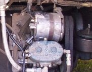 FWIW RCB | ||
| Wayne Buttress (Flyingbuttress)
Registered Member Username: Flyingbuttress Post Number: 3 Registered: 12-2009 Posted From: 99.196.224.56  Rating: N/A |
Hi Guys, My 4104/671 still has engine driver generator with separate regulator. Will a solenoid or isolator work with this setup? Wayne | ||
| Sean Welsh (Sean)
Registered Member Username: Sean Post Number: 1169 Registered: 1-2003 Posted From: 72.171.0.140 Rating: N/A |
Chuck, By "blowers" I meant for road air conditioning. Can't tell much from that photo. Does the alternator have a terminal marked "Relay" or "R" on it? If so, measure the voltage there with the engine running and tell me what you get. -Sean http://OurOdyssey.BlogSpot.com | ||
| R.C.Bishop (Chuckllb)
Registered Member Username: Chuckllb Post Number: 1393 Registered: 7-2006 Posted From: 75.211.122.187 Rating: N/A |
Sean...no former A/C...don't know about the "R"...don't remember one, but have never had the Alternator off the engine...just the regulator dismantled. Can check it, but not till next week. Thanx. RCB | ||
| Jim Wilkerson (Wagwar)
Registered Member Username: Wagwar Post Number: 107 Registered: 12-2009 Posted From: 99.109.187.242 Rating: N/A |
Sean wrote: "I added an on-off-on SPDT switch to my circuit so that I could force the solenoid to connect for emergency starting or to charge coach batteries from the house charger, or force it to disconnect for hill climbing and so forth." Sean, could you describe how to connect the SPDT switch in more detail? To force for emergency starting or charge both banks from the house charger, wouldn't you need a second 12V or 24V source that did not depend on the engine running? If you had an SPDT switch w/ a light, could you incorporate Don's suggestion: "A reminder lite would be a good idea wired so the lite is on if the engine is running and the override switch is preventing operation." Thanks in advance. | ||
| Sean Welsh (Sean)
Registered Member Username: Sean Post Number: 1170 Registered: 1-2003 Posted From: 64.150.176.78 Rating: N/A |
Jim, The common or wiper terminal of the switch goes to the solenoid coil. One of the two input terminals goes to the engine-derived source (oil pressure switch or alternator Relay terminal) and the other input goes to a direct source of battery power. Some prefer this latter input to be on a momentary toggle so that the solenoid can not accidentally be left connected full-time. You'll find these listed in catalogs as "(mom)-off-on". If you want a pilot lite you wire it in parallel with the solenoid coil, on the output side of the switch. -Sean http://OurOdyssey.BlogSpot.com | ||
| Jim Wilkerson (Wagwar)
Registered Member Username: Wagwar Post Number: 108 Registered: 12-2009 Posted From: 99.109.187.242 Rating: N/A |
Thank you, Sean. I may not understand the function of the mom - off - on, but wouldn't that prevent you from charging the coach batts from the house charger? Of course, in your bus you said you didn't want the flooded batts in the picture when you were charging the expensive AGM's. However, I don't have AGM's (yet). Also, my house charger is the Trace SW4024. If I were to use a normal on off on toggle so that I could charge the coach batts from the house charger, do I need to be concerned about placing too much demand on the Trace charger by combining the house and coach batt banks w/ the solenoid? Or is it simply a matter of time - taking longer to charge. I hope that makes sense... | ||
| Jim Wilkerson (Wagwar)
Registered Member Username: Wagwar Post Number: 109 Registered: 12-2009 Posted From: 99.109.187.242 Rating: N/A |
Please disregard my previous post. After more careful reading of this thread, I found my answer in one of Sean's earlier answers regarding combining the banks. Sorry for the confusion. | ||
| R.C.Bishop (Chuckllb)
Registered Member Username: Chuckllb Post Number: 1415 Registered: 7-2006 Posted From: 75.210.251.77 Rating: N/A |
Bottom line... I think...(unless youse guys convince me otherwise)... A small (8amp) three stage charger for start batteries...when shore power or generator is on) and a Victron Combiner (no diodes!!!) for when we are "underway".... Complaints, suggestions, comments welcomed and "SOLICITED"... BTW, HAMILTON MARINE sent me an email today...ALL is on sale, including the above ...and I am only a customer...thanx to FF years...yes many..ago! Thanx, RCB | ||
| Jim Wilkerson (Wagwar)
Registered Member Username: Wagwar Post Number: 117 Registered: 12-2009 Posted From: 99.109.187.242 Rating: N/A |
Sean wrote: "Alternatively, 12- and 24-volt fixed delay timers are relatively inexpensive and can be found at Neward, Allied, Del City, and others." How much fixed delay is necessary? Thanks | ||
| Sean Welsh (Sean)
Registered Member Username: Sean Post Number: 1185 Registered: 1-2003 Posted From: 72.171.0.141 Rating: N/A |
Jim, You want at least five seconds or so, otherwise the house batteries may get connected before the engine is even done cranking. I use a 30-second setting, because I want the engine fully up to speed and stable before putting extra load on the alternator. Anywhere between 5 seconds and two minutes would be fine. -Sean http://OurOdyssey.BlogSpot.com | ||
| Jim Wilkerson (Wagwar)
Registered Member Username: Wagwar Post Number: 120 Registered: 12-2009 Posted From: 69.152.39.142 Rating: N/A |
Thanks Sean. I installed all the wiring and components this weekend. I had to stop before I had this completely implemented because I was unsure of the proper method for a few things - electrically speaking: 1. The White-Rodgers solenoid (200A) has 5/16" posts for the battery cables. My battery cables are 4/0 w/ 1/2" ring terminals. Is it acceptable to bolt the 1/2" ring terminals to the 5/16" studs? Do I need to have the ring terminals on my cables changed ($)? Is there an adapter of some kind? Could I build an acceptable adapter? 2. I've also installed a Class T 300A fuse inline between the house battery bank and the TRACE inverter. However, I would also like to have a cutoff switch to completely separate the house bank and the inverter. Currently, the inverter is wired directly to the house bank through the fuse. A. Is it acceptable to put a cutout switch on this circuit? B. I plan to place the cutoff switch between the inverter and the Class T fuse on the + 24vdc cable. Is this the correct place? C. Does the cutoff switch need to have the same amperage rating as the Fuse? Is a lower amp rating acceptable? If so, what would that be? Thanks so much for your help. | ||
| Sean Welsh (Sean)
Registered Member Username: Sean Post Number: 1187 Registered: 1-2003 Posted From: 72.171.0.139 Rating: N/A |
Jim, Re #1: your main battery cables should not be involved here. You are adding a system to connect the two banks together. That probably requires only 2/0 cables, and you can put the appropriate size terminals on these. Do not modify your main battery cables. 2a: Yes. 2b: The fuse should be the first thing after the batteries. The main disconnect should be the next thing. 2c: The switch must have a rating greater than or equal to that of the fuse. -Sean http://OurOdyssey.BlogSpot.com | ||
| Jim Wilkerson (Wagwar)
Registered Member Username: Wagwar Post Number: 121 Registered: 12-2009 Posted From: 69.152.39.142 Rating: N/A |
Thank you Sean. Re #1: I currently have a 300Amp Isolator connecting the house bank with the start bank. The connections are: 1. a 4/0 cable with 1/2" ring terminals from the start bank to the isolator. 2. A 4/0 cable w/ 1/2" ring terminal from the isolator to the house bank. I was planning to simply replace the isolator with the solenoid, thus the problem with the stud size on the solenoid. You are suggesting that I replace the 4/0 cables with the appropriately terminaled 2/0 cables, correct? If so, so be it. However is there away to leverage the existing cables properly? Jim | ||
| Sean Welsh (Sean)
Registered Member Username: Sean Post Number: 1188 Registered: 1-2003 Posted From: 67.142.130.21 Rating: N/A |
Jim, If you already have the large cables, I would use them. Larger is always better if you can do it. Rather than change the terminals, if there is room on the 5/16 studs I would sandwich each 1/2" ring terminal between two copper washers with ID 5/16" and OD 5/8" so that you are getting good contact all the way around the terminals. Copper washers are a specialty item and you may have to hunt around for them. -Sean http://OurOdyssey.BlogSpot.com | ||
| Bill Gerrie (Bill_gerrie)
Registered Member Username: Bill_gerrie Post Number: 384 Registered: 3-2006 Posted From: 166.90.247.59  Rating: N/A |
Sean What about drilling a hole in a penny. I know they are not pure copper but I have used them for years without any problem. Bill | ||
| Sean Welsh (Sean)
Registered Member Username: Sean Post Number: 1189 Registered: 1-2003 Posted From: 67.142.130.21 Rating: N/A |
Bill, I would advise against that, for two reasons. Modern pennies are mostly zinc (~98%), with a very thin plating of copper. The first reason is that the resistivity of zinc is more than three times that of copper (59 n.ohms/m vs. 17 n.ohms/m). This can lead to ohmic heating of the "washer" and will degrade performance of the system. The second reason is that zinc is among the least noble of all common metals, and so any moisture in the area of the terminals can lead to galvanic corrosion and ultimately pitting of the zinc, in turn causing further ohmic heating and degradation of performance. If copper is unavailable, a pure aluminum washer would be the next best choice, with a resistivity of only 26.5 n.ohm/m. Aluminum is also more noble than zinc, although still not as good a choice as copper or silver. HTH, -Sean http://OurOdyssey.BlogSpot.com | ||
| R.C.Bishop (Chuckllb)
Registered Member Username: Chuckllb Post Number: 1422 Registered: 7-2006 Posted From: 97.215.50.188 Rating: N/A |
Good stuff, Sean... Thanx RCB | ||
| Bill Gerrie (Bill_gerrie)
Registered Member Username: Bill_gerrie Post Number: 385 Registered: 3-2006 Posted From: 166.90.247.59 Rating: N/A |
Sean Good info. I had no idea that there was such a high concentration of zinc in a penny. I wonder if the Canadian penny is the same. Bill | ||
| Sean Welsh (Sean)
Registered Member Username: Sean Post Number: 1191 Registered: 1-2003 Posted From: 67.142.130.30 Rating: N/A |
OK, the whole discussion of pennies versus washers reminded me that a buddy of mine, who consults in the marine industry, encounters stainless washers, which are about the worst conductor of all, in electrical connections all the time, and he has dozens of photos of them in his "hall of shame." Which prompted me to write on this subject for my monthly column in the November issue of Bus Conversions Magazine. In writing the column I realized that I mis-typed here earlier. The units of resistivity are nano-ohm-meters, not nano-ohms per meter as I wrote above. A common mistake, judging from the literature, owing to the fact that we tend to think in terms of length alone, but the units must also account for cross-section. I can no longer edit that post, so just read it as n.ohm*m rather than n.ohm/m. Sorry. -Sean http://OurOdyssey.BlogSpot.com | ||
| Bill Gerrie (Bill_gerrie)
Registered Member Username: Bill_gerrie Post Number: 387 Registered: 3-2006 Posted From: 216.198.139.38 Rating: N/A |
Sean Thanks for the info. It changed my way of thinking. I would have thought stainless was the best as they don't rust. Real copper from now on only. Bill | ||
| John Harrelson (Jharl)
Registered Member Username: Jharl Post Number: 99 Registered: 7-2005 Posted From: 74.166.245.86 Rating: N/A |
I am probably late in this thread but here are a couple of links to a 200A 12/24V relays cheap. This is a link to a forklift parts place. http://store.hgmforkliftparts.com/ProductSearch.aspx?k=SAS-4213 This is a link to a different distributor that have the specs of the relay above and many other relays. http://www.texasindustrialelectric.com/pdf/ametek_relays.pdf | ||
| Jim Wilkerson (Wagwar)
Registered Member Username: Wagwar Post Number: 157 Registered: 12-2009 Posted From: 69.150.233.21 Rating: N/A |
On a related topic to this thread: I implemented the solenoid and timer circuit to eliminate my batter isolator and create a relay to switch my rear a/c unit from the gen/shore side of my panel to the inverter side - when the engine is running. See discussion in this thread from last year. Thus, in theory, allowing me to run both a/c units from the inverter while running down the road and linking the coach and house batt banks when the engine is running. From my testing, the circuits are wired correctly. Last week, I finally had a chance to test the new 'systems' and it was a failure. I was able to run both a/c units while underway, but just a few minutes after starting them, the battery voltage was pulled down below 20 vdc and the inverter shut off with an overcurrent light. I tried just running one a/c and had the same problem. So, we shut them down and opened the windows. Flash forward to today and I went out to diagnose the problem. A/C units run fine on 30 A shore service and when genset is running. Current draw is around 15 A each and voltage is 'normal'. However, when I started the engine and linked the batt banks and turned on one of the a/C units, it ran for a couple of minutes and then everything went down - inverter would not come back on! So I started testing voltages and discovered that the screw post on the house batt that is connected to the inverter (house bank is 4 type 31 batts in series parallel for 24vdc) was melted and arcing. I've purchased a new batt, but in order to avoid cooking another one I wonder what other problem I should be looking for? If that connection to that post had been loose, would that explain the problem? Perhpas it became loose or I left it loose. In all other situations the inverter/battery system performs correctly. The only other variable that I can think of is there is also a solar controller connection on that same post for charging the batts from the solar panels. Any ideas? Thanks in advance. | ||
| R.C.Bishop (Chuckllb)
Registered Member Username: Chuckllb Post Number: 1546 Registered: 7-2006 Posted From: 97.213.99.104 Rating: N/A |
Thanx for this post, Jim...more or less why I started the thread...gee whizz... 9 months ago! RCB | ||
| R.C.Bishop (Chuckllb)
Registered Member Username: Chuckllb Post Number: 1581 Registered: 7-2006 Posted From: 97.224.107.228 Rating: N/A |
Sean...George...or someone....could you address this situation that Jim has encountered? Thanx! RCB | ||
| Tom Caffrey (Pvcces)
Registered Member Username: Pvcces Post Number: 1385 Registered: 5-2001 Posted From: 141.0.8.158 Rating: N/A |
I really doubt that the battery posts are built strong enough on those batteries to tolerate more than a few minutes of running two air conditioners. The inverter electronics is not going to look favorably on serious voltage sags caused by heavy loading of the house bank. A good target on maximum discharge rates is C/5, so if you have a 100 amp house bank, you should limit discharges to around 20 amps for continuing loads. Good luck on sorting this stuff out. Tom Caffrey PD4106-2576 Suncatcher Ketchikan, Alaska | ||
| R.C.Bishop (Chuckllb)
Registered Member Username: Chuckllb Post Number: 1584 Registered: 7-2006 Posted From: 97.215.44.130 Rating: N/A |
That's what I was looking for; thanx, Tom! Hope Jim will find it helpful, as well. RCB | ||
| Tom Caffrey (Pvcces)
Registered Member Username: Pvcces Post Number: 1387 Registered: 5-2001 Posted From: 24.121.238.44 Rating: N/A |
You're welcome, RCB. Heating and cooling are typically very expensive to do on battery power. For what it's worth. Tom Caffrey PD4106-2576 Suncatcher Ketchikan, Alaska |