| Author | Message | ||
| Brian Brown (Blue_velvet)
Rating: N/A |
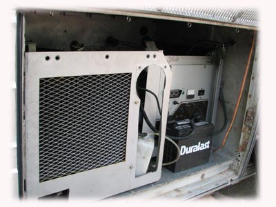
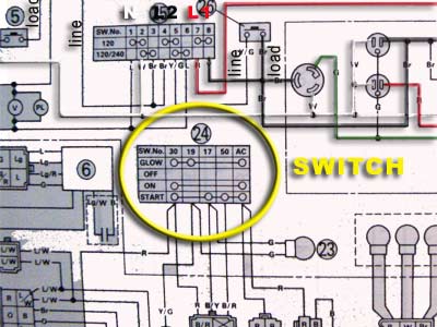
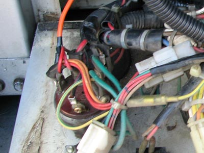
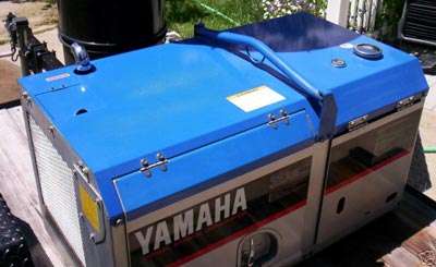
Hi All:  I've successfully transplanted a contractor-unit diesel genny (6.5kW, liquid-cooled, belt-drive alt.) into the old A/C condensor bay of my bus. It's plumbed into the main fuel tank and I added a little 4psi fuel pump. It's freakishly loud in operation, even though I added a beefy spark-arresting muffler, but I've got some ideas on how to quieten her. 3000rpm just makes a lot of noise... esp. without the hundred pounds of sheet metal enclosure I had to hack away to shoehorn it in there. At any rate, the issue de jour is how to add a remote start funtion to the unit. And Yamaha, the manuf. wants $450 for the unit! No way, I say. I'm thinking that I can accomplish the functions (GLOW/ OFF/ ON/ START) with some relays. Trouble is, I don't know how to design this system. I can wire and solder fairly well, but the concepts of relays tend to escape me. I have the old Onan remote start button and hour meter that could be pressed into service hopefully. The glow funtion could be accomplished with a momentary switch, maybe. I also bought a generic keyed starter switch. Below is a scan of the schematic I've been working with to re-wire the genny. Thanks for any insight! bb  | ||
| Richard Bowyer (Drivingmisslazy)
Rating: N/A |
I would suggest that before you do too much more, you run it for a few hours under full load. It may get too hot in the confined space, and the removal of sheet metal may have even compounded the problem. These industrial units are designed to operate in free space and they require a lot of air to cool them properly. As soon as you start adding noise reduction material, it may compound the heating problem. Much better to find out now, rather than after you have done a lot of additional work. Richard | ||
| Macgyver (91flyer)
Rating: N/A |
What kind of voltage and amperage is seen across those terminals? That will dicate what kind of relays and wiring will be required to operate that. Actually making it work shouldn't be too hard using a rotary switch combined with relays... Heck, that little thing is pretty easy. What gauge wires are currently at those posts? -Mac | ||
| Richard Bowyer (Drivingmisslazy)
Rating: N/A |
Check with Dick Wright at WRICO. He has a small remote panel with the proper switches. Probably will not even need any relays. Richard | ||
| Brian Brown (Blue_velvet)
Rating: N/A |
Mac: Most of the wires look to be #14. One on post #30 is a bigger one... maybe #12 or even #10. If I can just extend the wires about five feet, that could work, but I'm worried about too much voltage drop. Being able to start it from both places would be nice, also.  DML: The unit presently has gobs of free air circulation. Perhaps too much, because I have to load it up to get it to warm up and stop smoking. It didn't do that before I hacked it up. The enclosure before was amazingly confined with just a few screens along the bottom.  I won't have time to order anything from WRICO as I'm leaving on a 3000 mile trip Friday. If I have to forego remote starting, I guess I will, but it'd be a pain to stop and fire it up or turn it off. Thanks, bb | ||
| James Maxwell (Jmaxwell)
Rating: N/A |
BB: I built the remote for my 7kw Isuzu from 3 20 amp capacity DC switches. a single spst rocker wired from the 12v power to the on position of the keyed switch, a momentary for the glow function and another for the start function, essentially paralleled the switch that came with the unit. Power for the Preheat and start is jumped from the 12v source coming to the remote switchs. No relays, #12 wire about 20 feet. 1st switch for preheat came apart the 2nd time I used it, replaced, and no trouble in more than a year. I built a 2nd remote unit for the dash but have not wired it yet. I put a terminal strip in the cargo bay inside the enclosure for the remote unit that came with the genset and added an hour meter for it. Wire any number of remotes from the terminal strip. | ||
| Bob Vandawalker (Rav221)
Rating: N/A |
We used a auxilary solenoid and are only using a switch up front to trigger the solenoid. Also have a timer circuit to run the glow plugs and electric fuel pump before the starter engages. This seems to work really well the dozen times we've started it. | ||
| Brian Brown (Blue_velvet)
Rating: N/A |
Thanks, guys. I'll get happy with an aligator clip and see if I can accomplish what I want to do with switches and a terminal strip like JM suggests. I'll keep you posted, bb | ||
| John Jewett (Jayjay)
Rating: N/A |
Brian, your amp loads for starting are not heavy enough to require any relays or solenoids. Voltage drop is not a factor 'til you get into long wire runs in the neighborhood of 75 feet or so. Use two switches (DC rated natuarally) #1) SPST (single pole single throw) #2) SPDT/CO (single pole double throw spring loaded to center off. Switch #1 is the on/off for your fuel solenoid. This starts and stops the motor by controlling fuel flow. Run a fused 12V positive line to the top of the switch, and the wire from the bottom of the switch goes to the fuel cut-off solenoid. Switch #2 is a momentaty contact/center off. The down position is for the glow-plug pre-heat. The up position is for the starter solenoid (aka Bendix) There are three wires on this type switch: the center lug is fed with a fused 12V positive. The wire from the upper lug will go to the glow plug, and the wire from the bottom lug will go to the solenoid on your starter. (i.e. hold "down" for 20 seconds for pre-heat, then a brief push "up" 'til it starts. Use #14 AWG THHN wire and fuse it at 15 amps on each switch. Remember that SPDT/CO switches wire up backwards from the way you think they would. i.e. when the switch is pushed "up" the wire lug used is the the one that is "down". Don't try to feed both switches with one wire, since the loads are too high. Uncertain? Email me off the 'Board. Good Luck on the trip. ...JJ | ||
| James Maxwell (Jmaxwell)
Rating: N/A |
JJ: I agree, the spdt/co is a neater arrangement than my 2 spst/mom. But, nobody gave me a box full of heavy SPDT/CO and they did the ones I used. Like Brian, I wanted to get it done and that is what I had, it worked out ok, so I just left it that way. | ||
| Richard Bowyer (Drivingmisslazy)
Rating: N/A |
Any normal 10 amp switch will work very satisfactorily, they do not have to be heavy duty and they can be AC or DC rated. The voltage is not high enough to worry about contact arcing. Richard BTW, this is the same as the package that Dick Wright sells for a few bucks. | ||
| John Jewett (Jayjay)
Rating: N/A |
Richard, that small genset starter solenoid pulls about 40 amps when first engaged, and the possibility of an AC rated switch arcing and welding together is quite likely, hence my recommendation for the DC rated ones. If this occured on the fuel solenoid (mine pulls about 12 amps) he would not be able to conveniently and safely shut the genset off. Am extra $1.50 per switch is pretty cheap insurance. ...JJ | ||
| James Maxwell (Jmaxwell)
Rating: N/A |
JJ: Agreed the starter solenoid does pull that power, however, in glancing at the wiring diagram above, it appears to be very similar w/what my Isuzu has, and none of the 3 switch functions actually carry the power of the function being operated; they merely engage power solenoids or relays. I admit that I did not study the above diagram for precise detail and only speak to what I have. | ||
| Chuck Newman (Chuck_newman)
Rating: N/A |
Non-Electrical question: What is the issue with the generator smoking until a load is placed in it? Is this typical for diesel generators? Thanks, Chuck Newman Oroville, CA | ||
| Richard Bowyer (Drivingmisslazy)
Rating: N/A |
I agree with Mr. Maxwell and that is why I made my post. If you look at the partial wiring diagram supplied, it appears to be exactly (or similiar) to what many gensets utilize and it is strictly control circuitry, not DC power wiring. I have never seen anyone construct a remote control that would power high current draw items directly. 40 amps is not considered control circuitry in my opinion. Chuck, it is not uncommon for diesel gensets to smoke some when operating at no load or lightly loaded. Typically they will clear up when the load approaches 50%. Richard | ||
| John Jewett (Jayjay)
Rating: N/A |
Brian's photos show a multi-position switch and then heavy wiring fed from that switch. Nothing was said of "control voltage," only 12V DC line voltage. Ergo, I concluded that is what he meant, and based my recommendations upon the premise of switching the loads directly, merely supplanting a $450.00 mulit-position switch with a simpler, much more economical solution to his dilema. The above notwithstanding, I still contend that you should not use an AC rated switch on a DC circuit. The distinct possibility of failure and fire are too great. If there wasn't a pressing need, we would only have AC switches, since they are so much cheaper to manufacture. My recommendations stand as originally presented. Brian, if you wish to use the key switch, use it in place of the SPST switch #1. A good choice, especially if you have rug rats, or rambunctious canine traveling companions. There are many configurations available for this situation, and due to space limitations on my panel, I have given you the one I chose, and I don't claim it to be the only or best one available for your application. Cheers...JJ | ||
| Brian Brown (Blue_velvet)
Rating: N/A |
Thanks, folks. The past few days I got consumed with the critical items on my maint. list (upper rad. hose replacement, new sender and temp. gauge, etc.). It always takes longer than what I plan to finish each task. Hopefully, I'll still have time to do this remote start project tonight. The switch ideas and info are great. JJ, I would like to use my keyed switch, if possible, because of my three little ones ("What's this button do, Dad?"). The one I bought is a generic starter replacement switch... no listing of rating on it. It has four positions: OFF/ACC/IGN/START and I was hoping to make it OFF/GLOW/ON/START. I think I can do this with the info you and others gave me. Thanks, all! bb | ||
| JR
Rating: N/A |
I've done what you are trying to do with the same Yamaha EDL6500. Used an outboard boat motor wiring harness (one 12 ga, eight 16 ga wires in a nice cover). Used one toggle and two push buttons. The "on" position is uses a good bit of power due to the two solenoids that control the idle and full load operation. Wired the toggle as an on/off, one button goes to the stater and the other does the glow plugs. Remaining wires operate another idiot lite module identical to the one in the panel. As you did, I separated the generator, engine, and radiator assembly and put those in the old AC condenser compartment. The electrical panel is mounted inside the first bay and is functional. I tapped the control wires thru automotive (Bosch style) 12 V relays. That keeps the load on the wiring minimal. Used 3 relays, ignition, start, glow plugs. Just tapped the relays controls back into the Yamaha key switch. Works great. I didn't use the high low idle, it stays on high, and it is always on 120 only volts. Works great so far. It is noisy, but that's the price of the high RPM diesel. It is very frugal on fuel. Operates both ACs without a problem. Runs whenever I'm on the road and need AC. No bus AC. The generator conrol wires, starter, ignition and glow plugs, will require 12 ga to operate as a remote, if you don't use relays. Much easier to use a few relays and smaller, more manageable wiring. The Onan and other remotes often don't have a glow plug switch. And, they use a mag style "off" which will short to ground. Yamaha doesn't do it that way. Yamaha is like an automobile. Hot for ignition on. I have a service manual with the wiring schematic and will fax you a copy of the wiring if you're interested. P mail me if so. BTW, you could use any automotive type keyed ignition switch, or marine as long as it has B+ to ignition or accessory terminals. Don't use "mag" terminals if present. JR | ||
| Bruce Henderson (Oonrahnjay)
Rating: N/A |
Brian said: "I bought is a generic starter replacement switch... no listing of rating on it. It has four positions: OFF/ACC/IGN/START and I was hoping to make it OFF/GLOW/ON/START. " __. Unless you have an unusual switch, this won't work. You want a switch that gives you 1) Everything off -- 2) Glow circuit (and nothing else) on -- 3) Ignition (and nothing else) on -- 4) Start, power to the starter and "ignition on" __. But most (if not all) key switches that I know of will give you 1) Everything off -- 2) Glow circuit (and nothing else) on -- 3) Ignition (*AND acc/glow circuit) on -- 4) Start, power to the starter and "ignition on" __. A switch that works the way that you describe would let you listen to your radio only while the engine off, then it would switch the radio off when the engine was started. Obviously, you're not going to find many of those. (If you have found a switch wired like the upper 1-4 above, then that's good -- I just don't think they're common, if available at all.) __. Sorry if this is obscure, it's hard to describe wiring/switch logic in words. | ||
| James Maxwell (Jmaxwell)
Rating: N/A |
BB: On the generic auto key switch, does not the ACC stay hot in the IGN position? If so, u have constant glow plug with that arrangement. I can't recall this detail from my memory bank (brain-bad sector) so meter it beforehand. The keyed switch that came with my genset was of the ACC/off/ign/start variety, glow/off/on/start | ||
| Bruce Henderson (Oonrahnjay)
Rating: N/A |
__. Just had a thought, Brian. You could use an ordinary key switch with a "momentary contact -- push-button switch" in series with the accessory circuit. __. To energize the glow circuit, switch the key switch to "acc" and push the button. Then release the button when the glow plugs are warm, go to "start" then release the key as you would in any car. This way, you could start the genny when the engine is warm without using glow (just don't push the button). Also, if a yard ape pushes the button when the key switch is off, nothing happens. __. Cheap, simple, and good. | ||
| Brian Brown (Blue_velvet)
Rating: N/A |
JM and Bruce, you're correct on my generic keyswitch. I did some continuity testing tonite on it. And you're right, it makes sense from an automotive standpoint. So, I'll still need a momentarty switch like Bruce suggests for the glow plugs. JR, nice to know there's somebody else out there with my genset! Your remote start sounds elegant. I haven't quite gotten my hands around relays and wiring them yet, though. I'll probably just pull four 12ga wires for now and run direct. I think I'll just need about four feet or so from the panel. I need to figure out what the "mag" terminals are you mention. DC wiring is still a bit overwhelming to me. I do have the Owners and Service Manuals. Thanks, though. After my trip I'll send along some pics of my installation. I used an Onan spark-arresting muffler and a 1.5" tailpipe. The exhaust is pretty quiet, but the intake and gen. noise are very loud and come right through the condensor screen. On the other side of the bus, though, it's just the dull sound of the exhaust you hear. I'm thinking if I keep the rad. exhaust clear, I could baffle the other half of the opening and tone down the racket some. Thanks for the advice, guys! bb | ||
| JR
Rating: N/A |
One option would be to purchase a Yamaha EDL6500 ignition switch, which has a glow, off, on, start postions (same as Yamaha original in the control panel). Install it in the bus dash and match the wiring with the panel switch. 10 ga hot, 12 ga for rest. That would give a keyed switch with all necessary functions. An automotive switch would require the use of a MOM toggle for the glow plugs. Some outboard motor ignition switches have a "push to choke" feature which would allow use of the glow plugs without additional switches. The "choke" position could be used for the glow plugs. If you use any other monitors, a dedicated ground wire would be a good idea. While I'm not familiar with American manufactured gensets, the Japanese generators have high capacity wiring that will carry a higher amp load than the size would suggest. These wires should be modified carefully. John Deere makes a small key switch that fits a 5210 tractor that has all necessary terminals and a glow plug function. | ||
| JR Rating: N/A |
As an aside to this specific Yamaha generator wiring, the Yamaha key switch is not a "control" wired switch. It is a 12V hot switch that directly controls all of the glow plugs, starter solenoid, and the idle and max RPM solenoids...and the idiot lights (low oil, hot water, not generating). The gen light is wired from one of the stator windings. The generator will shut down if it loses 110AC as the radiator cooling fan is 110 VAC that runs all the time. One thing that does not sound correct is the smoking. My identical generator to yours does not smoke except immediately when starting and accelerating to normal speed. It clears up immediately. Have you modified the air intake? I would recommend using the original air filter, which you probably used, with the long intake hose. The air filter can has not been reversed? The intake is on the side (with the water drain pointing downward), and the outlet (to the engine) is on the end of the filter case. You may need to drop the fuel pressure. You state you used a 4 lbs pump? I used a 2 lb pump. The generator will operate on o.1 lb. It was designed to be gravity fed. Return line isn't kinked? | ||
| John Jewett (Jayjay)
Rating: N/A |
Hey, JR, having the right switch doesn't seem fair somehow. If it was easy everybody would be dong it. Glad to know about it, for future reference. BB-The world's absolutely best genset muffler is off a Honda Goldwing bike. Pricey ? Yes, but sooo quiet. ...JJ |