| Author | Message | ||
| Jim Huskins (Lostranger)
Registered Member Username: Lostranger Post Number: 19 Registered: 8-2007 Posted From: 70.109.24.220 Rating: N/A |
I've put off the permanent wiring as long as I can, but I'm fuzzy on some of the details. Right now I'm trying to figure out how to wire a 2000 watt sine wave converter so it won't try to start the two roof air conditioners when we're not on shore or generator power. We do some dry stops when we need a little AC to run a small TV, a DVD player and a lap top. Lighting is all DC and refrigerator is propane. We don't use microwave, hair dryer, coffee maker, etc. I want to run the TV et. al. on shore power when available, so where do I hook the inverter? I saw a setup on line where a guy used a 3 phase panel with two legs dedicated to shore power and the third "switchable between shore power and inverter." That's not what I want to do. Do I need a sub panel with some sort of transfer switch? I've tried to find answers on the web, but I'm still confused. Jim | ||
| Dave Walker (Chrome_dome)
Registered Member Username: Chrome_dome Post Number: 30 Registered: 3-2010 Posted From: 67.174.144.159  Rating: N/A |
Jim This picture gave s a good idea of where it all goes in our bus. Hope it helps. Dave 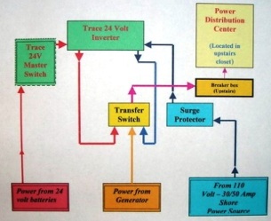 | ||
| FAST FRED (Fast_fred)
Registered Member Username: Fast_fred Post Number: 1191 Registered: 10-2006 Posted From: 99.12.241.82  Rating: N/A |
OF course other ways exist , simply using a mask on the panel that allows the inverter to work IF the Air is shut off. Then there are plugs , unplug the Air, plug in the inverter. KISS , you have to buy it and fix it, FF | ||
| Debbie and Joe Cannarozzi (Joe_camper)
Registered Member Username: Joe_camper Post Number: 287 Registered: 10-2006 Posted From: 99.23.149.181  Rating: N/A |
Fred on our bus the main fuse panel has a 30 amp breaker for the a/c current feeding the inverter. The a/c current flows thru the inverter then out and on to a sub panel where all the breakers for everything I want to run off that inverter are located. Even though I do not run air conditioners on the inverter I still have to manage power when it is inverting. The micro, the toaster, the fridge, outlets, ect All things that IMO need to be powered off of it. With a 2500 watt inverter they can not all run togeather but all are components that need inverter power for convienience. A bigger inverter or another one would help dramaticly but so does the costs. Although all these seprate circuts on that sub panel and are protected with 20 amp breakers in that inverter sub panel I am restricted by the 25 amp breaker located on the inverter itself. For example although the toaster has a 20 amp breaker and so does the micro if I try to run them togeather off of inverter power it is more than the 25 amp breaker on the inverter can handle. I have friends with 2 4000 watt inverters and even they need to manage power they get 60 or 70 amps max between them still short of the 100 amp needed to overcome the managment Some inveters have an automatic internal switch some do it with an auto external switch and some buses use a manual external switch usually located at the control panel. We have an automatic internal switch and it is very convienient. We never turn our inverter off. If it is getting shore or gen power it is charging and as soon as you stop a/c current comming in it auto switches into inverter mode. This wiring style is very very simple to install and very easy to understand. Hope that helped. On a side note I have learned when we get to a campground and hook up to shore I take the a/c current feeds into and out of the inverter and disconnect them from the inverter and hook them to eachother effectivly bypassing that inverter and then we do not have to manage power any longer because it is inconvienient to have to be forced to only use one kitchen appliance at a time when on shore power simply because the power is flowing thru the inverter. This also comes with compramise because by doing this we also loose the battery charging mode but a redundant small external battery charger on the house batts solves that. Sorry for the spelling all. | ||
| Debbie and Joe Cannarozzi (Joe_camper)
Registered Member Username: Joe_camper Post Number: 288 Registered: 10-2006 Posted From: 99.23.149.181  Rating: N/A |
An inverter by-pass is an important component that many folks both do not get or realize the convienience of before getting a bus or installing the inverter. Sure you can power ALL your accesories off that inverter and practice power managment depending on the size of that inverter and that is really very convienient going down the road or boon-docking. BUT............ remember, when you get to a campground and there is no by-pass switch you are STILL FORCED TO MANAGE POWER cause it flows THRU the inverter and that is limited to the amperage of the breaker directly on that inverter itself. Being able to by-pass ours allows us to go from 25 amp the size of the inverter breaker to 30 amp the size of the breaker on the main panel feeding the inverter. I misspoke slightly in the previous post we still have to manage power even when we by-pass it but with 30 amps available (from the main panel) we can run 2 big draws togeather where 25 amp (on the inverter) is not quite enough and that makes things way more convienient. Another good reason for a by-pass is if your fridge is not propane and on that inverter and the inverter goes down you loose power to the fridge and your hooking the fridge to an extension cord and looking for an outlet not powered thru that circut to get it running again and that sucks. | ||
| Dave Walker (Chrome_dome)
Registered Member Username: Chrome_dome Post Number: 31 Registered: 3-2010 Posted From: 67.174.144.159  Rating: N/A |
So Joe Some of our lights (In the Bath)come on when we are plugged into our house 50 amp and the inverter is switched off but not the kitchen or desk lights. I switch the inverter back on and then I can turn the rest on and looking at the wires for the second ones they have braided wire and the bathroom and the plugs have 14-2 w/G and 12-2 w/G Romex. In wiring in new lights should I wire with both so that they work either way? Dave | ||
| Jim Huskins (Lostranger)
Registered Member Username: Lostranger Post Number: 20 Registered: 8-2007 Posted From: 70.109.24.220 Rating: N/A |
I'm loving this helpful discussion and the great info in response to my original question about inverter hookup. I like hands on control, and I'm thinking that I'd like to try a manual transfer switch to select between generator and shore power, and a switchable sub panel to run the few circuits we would want to drive with the inverter. I could turn off the sub at the main panel and then turn on the inverter. Maybe a second transfer switch between the main and sub panels would be even better. Any thoughts? I also have another question. Our bus has a 24v starter, but all the lights are 12v. Our house system is 12, and it's too late to change that. I found a 12v output stud on the 200 amp alternator and ran a wire from that to a common point with the output from my Iota converter/smart charger. My theory was that the bus alternator could charge the house batteries while the engine is running. It does so, but when the engine is not running, the house batteries apparently feed back into the bus system, drains the house batteries (when not on shore power), and makes some bus circuits hot that should be cold with the battery switch off. What do I need to stop the back flow? I hear about battery isolators and one way diodes and such, but I have no idea what I need on the 12v generator feed to fix this problem. TIA Jim | ||
| Debbie and Joe Cannarozzi (Joe_camper)
Registered Member Username: Joe_camper Post Number: 291 Registered: 10-2006 Posted From: 99.23.149.181  Rating: N/A |
Dave it sounds like the inverter does not have an automatic internal switch so if it is not on power will not just flow thru it. Jim yes you are suggesting another fashon of an inverter by-pass. Just to clarify We too have a manuall switch that goes shore/off/gen. It is our inverter that has a automatic switch. If it senses a/c current from either source it allows that current to just flow thru and the battery charger is powered up and if that feed stops it immidiatly begins inverting. It is a quick enough switch that it usually does not interupt anything running while the switch takes place. I have both 24 and 12 volt house batteries and we are tapped in at the vanner equalizer and we do not have your issues. A solonoid in the feed to the batts allows me to open that circut when I stop. | ||
| Debbie and Joe Cannarozzi (Joe_camper)
Registered Member Username: Joe_camper Post Number: 292 Registered: 10-2006 Posted From: 99.23.149.181  Rating: N/A |
Dave I would not wire both feeds to 1 source unless you were completly sure there was no way you could even mistakenly create a 240voolt situation in any configuration. | ||
| Dave Walker (Chrome_dome)
Registered Member Username: Chrome_dome Post Number: 35 Registered: 3-2010 Posted From: 67.174.144.159  Rating: N/A |
Joe Thank you , yes thought about that after I asked. We do have a remote for our Freedom 2500 interface inverter and when I switch it to DC it also show AC and I can hear the inverter switch on and off when needed. So all works when it is on AC DC ( The inverter ,not he group{:>)and shows the house Batteries are charging but the are shot and we knew that when we bought it which we will buy 4 new T-108s 6V when can afford. So I put it on AC only while working on the conversion. Plugs all work jut not the lights & bath fan which only work when on both AC-DC. Fan works on AC but a lot slower and lights come on but very weak on AC. Dave | ||
| Jack Fids (Jack_fids)
Registered Member Username: Jack_fids Post Number: 84 Registered: 1-2009 Posted From: 69.171.160.20  Rating: N/A |
I really hope someone can diagram this simply for you Dave because in about 2 weeks I am going hooking up my pair of inverters and I'm sure I'll be echoing this post all over again! | ||
| Dave Walker (Chrome_dome)
Registered Member Username: Chrome_dome Post Number: 37 Registered: 3-2010 Posted From: 67.174.144.159  Rating: N/A |
Jack, why don't you just copy and paste, it is easier than echo-----ing. {:>] | ||
| Jack Fids (Jack_fids)
Registered Member Username: Jack_fids Post Number: 86 Registered: 1-2009 Posted From: 69.171.160.20  Rating: N/A |
Dave-ve-ve, Does your Bus have nail-proof tires? BTW what's your home address? | ||
| Sean Welsh (Sean)
Registered Member Username: Sean Post Number: 1096 Registered: 1-2003 Posted From: 67.142.130.45  Rating: N/A |
The 12-volt terminal is not for charging. You can destroy the alternator by doing this. The 12-volt terminal is a "Relay" terminal. It's sole purpose is to provide a low-current signal that the alternator is producing output. The only thing that should be connected to this terminal is a 12-volt relay. On many coaches, the 12-volt relay is then used to signal the HVAC system that the blowers can be run (you don't want those running on batteries alone) and also to drive the "Not Gen," "No Charge" or similar tell-tale on the dash. If you connected this terminal to a battery, then, yes, it will feed through the alternator to the main output terminal. -Sean http://OurOdyssey.BlogSpot.com (Message edited by Sean on May 30, 2010) | ||
| Bruce Henderson (Oonrahnjay)
Registered Member Username: Oonrahnjay Post Number: 547 Registered: 8-2004 Posted From: 70.61.105.213  Rating: N/A |
Sean, you wrote "The 12-volt terminal is not for charging. You can destroy the alternator by doing this. The 12-volt terminal is a "Relay" terminal. It's sole purpose is to provide a low-current signal that the alternator is producing output. The only thing that should be connected to this terminal is a 12-volt relay." I think I'm missing some background info to understand this. Is this for a 24v alternator? (ie. Does a 24v alternator have a 12v "signal" terminal?) Or is the "R" terminal in addition to the "F" terminal on a 12v alternator (and both in addition to the large output terminal)? Thanks, BH NC USA | ||
| Sean Welsh (Sean)
Registered Member Username: Sean Post Number: 1097 Registered: 1-2003 Posted From: 67.142.130.45  Rating: N/A |
Bruce, I'm assuming he has a 24-volt alternator, since he's got a 24-volt coach with a 24-volt starter. Also from the way he wrote that he "found" a 12-volt "post," which I heard as "in addition to the 24-volt post." But I concede that these are assumptions, and I know nothing about Flxible Metros, so perhaps I should confirm: Jim, is your 200-amp alternator a 24-volt model? Going on this assumption being correct, then any 12-volt terminal is a "Relay" or "R" terminal and its purpose is to signal that the alternator is producing output. For the technically inclined, this is actually a half-wave rectified signal from one single diode (of a total of six) in the alternator. As such, the most current it could possibly produce would be one-sixth the total, and it's not exactly 12 volts, nor is it a smooth DC output (neither is the main output, but the fully rectified, three-winding output is much smoother than a half sine-wave). On a 12-volt alternator, the Relay or R terminal would produce roughly 6 volts, and systems that utilize such an output use 6-volt relays. Trying to draw any real current from a relay terminal will have the effect of overloading that one winding, and could end up burning out the winding, or at least that diode. FWIW. -Sean http://OurOdyssey.BlogSpot.com | ||
| Bruce Henderson (Oonrahnjay)
Registered Member Username: Oonrahnjay Post Number: 548 Registered: 8-2004 Posted From: 70.61.105.213  Rating: N/A |
Thank you, Sean. That makes perfect sense. I'd seen things plugged into the "R" terminal but I didn't know how it was energized or how its signal is used. Sorry about my ignorance but this has decreased that, at least in some small way. BH NC USA | ||
| Sean Welsh (Sean)
Registered Member Username: Sean Post Number: 1098 Registered: 1-2003 Posted From: 67.142.130.37  Rating: N/A |
Happy to help. Since a picture is worth a thousand words, you can also go to Delco-Remy's site and download the service manual for many of their models (available here: http://www.delcoremy.com/manuals.aspx), which often will have an internal alternator wiring diagram. For example, here is the manual for the 50DN high-output brushless alternator that many of us have on our coaches: http://www.delcoremy.com/pdfs/service_manuals/current/1G-254.pdf If you scroll down to page 3, at the bottom of the page on the left is the wiring diagram. You can see there where the "R" terminal is connected inside the alternator; basically it is the unrectified output of a single winding. Because of the way "ground" is generated in the rectifier, this ends up being a half-wave rectified DC signal of about half the main output voltage. The closed-circuit path between this terminal and "ground" involves only two "lower" diodes. You can also see from this drawing how connecting a 12-volt battery (or other 12-volt supply such as the charger mentioned) between ground and this terminal will send 12 volts through the lower right diode to the main output terminal and thus energizing the whole chassis system with 12 volts. Many relays used to power up chassis loads will not close with only 12 volts, but there are plenty of other things to go wrong. -Sean http://OurOdyssey.BlogSpot.com (Message edited by Sean on May 30, 2010) | ||
| Luvrbus (Luvrbus)
Registered Member Username: Luvrbus Post Number: 895 Registered: 8-2006 Posted From: 74.32.84.228 Rating: N/A |
It is ok to hook a tach to the R terminal that is done every day not my choice as I like pulse generators off the engine | ||
| Sean Welsh (Sean)
Registered Member Username: Sean Post Number: 1099 Registered: 1-2003 Posted From: 72.171.0.149  Rating: N/A |
Sorry, yes, a tach is the other common item connected to the R or Relay terminal. Again, these draw almost no current. As I said earlier, this ia a half-wave signal, which almost any tach will see as a "pulse." All you need is the ratio of engine RPM to alternator RPM to calibrate the tachometer. -Sean http://OurOdyssey.BlogSpot.com | ||
| Jim Huskins (Lostranger)
Registered Member Username: Lostranger Post Number: 22 Registered: 8-2007 Posted From: 68.238.117.228 Rating: N/A |
I certainly wish I had asked here before tapping my generator. It is a 24v, 200 amp gear driven unit. I had already unhooked the wire from the 12v tap, but I appear to have done damage to the alternator. What's involved with fixing that? Jim | ||
| Pete/RTS Daytona (Pete_rtsdaytona)
Registered Member Username: Pete_rtsdaytona Post Number: 614 Registered: 1-2005 Posted From: 97.104.18.110  Rating: N/A |
Tach Hookup info 50DN - Alternator "R" Terminal hookup - output is a half wave pulse @ half the Main output voltage Most 24 volt - ?V92->(2.94 (53/18) gears & 6 pulses per rev=17.66 pulses/rev) Most 24 volt - 8v71->(2.75 (55/20) gears & 6 pulses per rev=16.5 pulses/rev) Most 12 volt - 8V71->(2.29 (55/24) gears & 6 pulses per rev=13.75 pulses/rev) | ||
| Sean Welsh (Sean)
Registered Member Username: Sean Post Number: 1101 Registered: 1-2003 Posted From: 67.142.130.44  Rating: N/A |
Depends. What are the symptoms you are experiencing? There are two problems you might have caused by over-drawing from the Relay terminal. One would be a burnt diode (or maybe two), the other would be a burnt winding. Burnt diodes are easy to diagnose and replace. The procedure is in the service bulletin; for example, the one I linked earlier explains how to test and replace diodes on the 50DN. If it's a bad winding, then your best bet would be to trade it for a rebuilt unit. That said, almost any alternator shop can re-wind these, but I would guess that to be as much or maybe more than a rebuilt. What model alternator do you have? Should be on a metal plate riveted to the body. -Sean http://OurOdyssey.BlogSpot.com | ||
| Jim Huskins (Lostranger)
Registered Member Username: Lostranger Post Number: 23 Registered: 8-2007 Posted From: 68.238.117.228 Rating: N/A |
Sean asked: "What model alternator do you have? Should be on a metal plate riveted to the body." I'll check it out on Tuesday and post to this list. This bus is a 1987 Flxible Metro transit with a 6v92 TA. Don't know if the alternator is original. Jim |