| Author | Message | ||
| Dave Walker (Chrome_dome)
Registered Member Username: Chrome_dome Post Number: 86 Registered: 3-2010 Posted From: 67.174.144.159  Rating: N/A |
Sorry for the long Post but I am at a loss? Anyone want to venture a guess. We have a MC5C. We have been converting to go full time soon. In working on it I have been plugged into the Garage and have been able to use everything electrical AC and DC. Hadn't been able to unplug and use anything off JUST the Batteries because they were killed by non use and no charge for 2 years before we bought it. We figured when the time came we would buy new batteries and put them in and should be able to dry camp etc. off them. Inverter is a 5 year old big black and ugly Heart Interface Freedom 20. Has a 25 amp fuse and an n Off switch on end. Doesn't seem to make any difference if it is in on or off position. Have a Remote panel on the wal for it also. Pro Mariner Charger 24/30 Vanner 60-2A Voltmaster Input 20-35V DC output 50 MV, says Current max limited to 20 Amp Breaker I finally went to Battery store Friday and bought 4 new US 2200 deep cycle batteries, hook them up like the other ones in Series and parallel after cleaning, priming and painting the compartment. I unhooked from the garage box and the remote on the wall went dark but I noticed the DC lights Refrig, stove lite etc. But no AC lights work or AC plugs either. They all did when plugged in to the garage power. I turned the Inverter remote on and didn't here the Inverter fan and the Remote LED 's were lighting up the AC then Overload back and forth and the inverter light was not blinking which was usual for it. Normally the Inverter and AC lights were on and then the Battery DC lights to show how much was used up etc. I traced the wires to make sure they were all hook up and they are, from the batteries to the inverter. From the inverter to the AC circuits through the transfer box where all come into and go out to breakers, Generator etc. But still no AC upstairs. I hear the inverter kick in when we are hooked to house power but when unhooked no noise for it. But DC circuits come on and I think are running from batteries with no inverter? Don't know where to go from here. Is the Inverter shot or gone but then why is it working when plugged in and not working when disconnected? Any idea would be appreciated. Thanks Dave (Message edited by chrome dome on October 02, 2010) | ||
| Jack Fids (Jack_fids)
Registered Member Username: Jack_fids Post Number: 168 Registered: 1-2009 Posted From: 69.171.161.38  Rating: N/A |
This: "...hook them up like the other ones in Series and paralle.." I think, will cause some confusion, at least it does me.. Pic's tell the story so much better imho | ||
| thomas flocks (Taflocks)
Registered Member Username: Taflocks Post Number: 369 Registered: 9-2009 Posted From: 74.76.246.165 Rating: N/A |
ask sean....... | ||
| Dave Walker (Chrome_dome)
Registered Member Username: Chrome_dome Post Number: 88 Registered: 3-2010 Posted From: 67.174.144.159  Rating: N/A |
I did Tom on other board and are working on it. A couple of people said that these older ones have 2 big relays and sometimes you have to give them a whack so to speak,LOL Sean told me to back trace after disconnecting all branch lines and then start adding them back in to see if there really is an overload and will star doing that today. Jack I will add some pic's if you would like but it is in a very hard place to get good ones. Dave 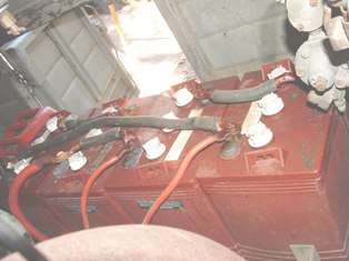 | ||
| Sean Welsh (Sean)
Registered Member Username: Sean Post Number: 1180 Registered: 1-2003 Posted From: 67.142.130.16  Rating: N/A |
"ask sean......." I actually answered this identical post on "the other board" and Dave has responded there. I gave him some to-do's and am waiting for the results. Not playing board favorites, it's just a matter of wherever I happen to see the post first. One of the inherent downsides to cross-posting. -Sean http://OurOdyssey.BlogSpot.com | ||
| George M. Todd (George_todd)
Registered Member Username: George_todd Post Number: 1108 Registered: 8-2006 Posted From: 99.62.8.87 Rating: N/A |
Not to butt in, But the way the connections look in the picture, it can't work! It appears that all of the batteries are installed in the same orientation, with all of either the positive, or negative terminals in a row, or close to the camera. For the sake of discussion, the first two batteries on the right have their positive terminals connected to red cables going somewhere, and their negative terminals connected together. If that IS the case, it WON'T work! If the center two batteries are turned 180, then the first and second from the right are correct for 12 Volts. If the last battery on the left is oriented the same as the first on the right, and I see it correctly, the whole system can't work for 12 Volt series parallel. Series-Parallel with 4-6 Volt batteries for 12 Volts requires two batteries with their POSITIVE terminals connected TOGETHER, and their NEGATIVE terminals connected TOGETHER. Then the other two batteries must be connected the same way. Then connect the POSITIVE terminals from one set of batteries to the NEGATIVE terminals of the other set of batteries. Connect the remaining NEGATIVE terminals to ground, and the remaining POSITIVE terminal is your hot connection. HTH, G | ||
| Sean Welsh (Sean)
Registered Member Username: Sean Post Number: 1182 Registered: 1-2003 Posted From: 67.142.130.16  Rating: N/A |
"It appears that all of the batteries are installed in the same orientation," George, it looks to me like the two center ones are one way, and the two end ones are the other. You can't tell just by the terminals, because with diagonal terminals such as these, the battery looks the same from either end. I am looking at the labels... -Sean http://OurOdyssey.BlogSpot.com | ||
| George M. Todd (George_todd)
Registered Member Username: George_todd Post Number: 1109 Registered: 8-2006 Posted From: 99.62.8.87 Rating: N/A |
Sean, I guess we're reduced to guessing... In my 4th paragraph, I did say that "...If the center two batteries are turned 180..." IF the end two batteries have the positive terminal toward the camera, and the middle two have the positive away from the camera, they are correctly connected for 12 Volt series parallel. The only issue, which may or may not be an issue, is the 3rd cable, which is electrically the same as the middle cable. Is there something connected to the last terminal we can't see? Happy guessing, George | ||
| Sean Welsh (Sean)
Registered Member Username: Sean Post Number: 1183 Registered: 1-2003 Posted From: 67.142.130.16  Rating: N/A |
"IF the end two batteries have the positive terminal toward the camera, and the middle two have the positive away from the camera, they are correctly connected for 12 Volt series parallel." I read it as the other way, with the end two having - towards us, and the middle two having + towards us, and I see a large red positive take-off on the closer terminal of the second battery from left. The ground terminal would appear to be the closer terminal of the leftmost battery. The two smaller cables, attached to the closer terminals of the third and fourth batteries respectively, are the + and - take-offs for a smaller load or charger, presumably. Perhaps Dave will chime in and confirm or refute. -Sean http://OurOdyssey.BlogSpot.com | ||
| Dave Walker (Chrome_dome)
Registered Member Username: Chrome_dome Post Number: 89 Registered: 3-2010 Posted From: 67.174.144.159  Rating: N/A |
Sean George I am back sorry We had to help someone we know move who just lost their home, tired and will try to explain. No George they are as Sean said the end one closest to the right side of the picture is Neg the 2 in the middle are positive and the furthest one is neg and the other side away from the camera are the opposite. 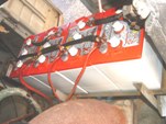 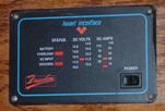 (Message edited by chrome dome on October 03, 2010) | ||
| Dave Walker (Chrome_dome)
Registered Member Username: Chrome_dome Post Number: 90 Registered: 3-2010 Posted From: 67.174.144.159  Rating: N/A |
Sean you are right I will put in a diagram of what I took off and the same I put in with the new Red top ones and the other pic is of that thing between the Positive cable and the cable going to the inverter. 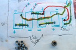 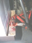 Dave | ||
| Dave Walker (Chrome_dome)
Registered Member Username: Chrome_dome Post Number: 91 Registered: 3-2010 Posted From: 67.174.144.159  Rating: N/A |
Sean; This pic is what I thought was the trasfere switch but bob said maybe not? Dave 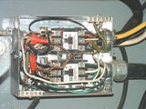 | ||
| Dave Walker (Chrome_dome)
Registered Member Username: Chrome_dome Post Number: 92 Registered: 3-2010 Posted From: 67.174.144.159  Rating: N/A |
Sean affirmative the 2 RED smaller cables go up to the charger that charges all batteries here is a picture of it. Dave 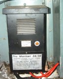 | ||
| George M. Todd (George_todd)
Registered Member Username: George_todd Post Number: 1111 Registered: 8-2006 Posted From: 99.11.187.202 Rating: N/A |
Regardless of which terminals face the camera, the large red cable is connected to a battery terminal and a jumper. The middle smaller red cable is connected to the other end of the same jumper, and a battery terminal, which is why I said they are electrically the same. | ||
| Dave Walker (Chrome_dome)
Registered Member Username: Chrome_dome Post Number: 93 Registered: 3-2010 Posted From: 67.174.144.159  Rating: N/A |
George; Yes I know but that smaller one is the positive going to the Battery charger not the inverter and the big red one is going to the inverter. the other small red one is the negative cable also going to the charger is that bad or wrong? Dave | ||
| George M. Todd (George_todd)
Registered Member Username: George_todd Post Number: 1112 Registered: 8-2006 Posted From: 99.39.12.79 Rating: N/A |
Dave, Once we saw the diagram, everything became clear, and all is correct. As to where we go from here, a voltmeter will be necessary. It would be handy to read the house battery voltage without the bus being plugged in. Then plug into shore power, and read again. You should read about 12 Volts disconnected, and at least 13 Volts plugged in to shore power and charging. The 25 amp fuse mentioned will have to be in the 120 VAC circuit. Please have the power off, and remove the fuse. Check it with the multimeter in the Ohms position. A reading of less than 1 Ohm means the fuse is good. No change in reading when touching a lead to each terminal of the fuse means the fuse is bad (open.) Lets go this far, then figure out whats wrong from there. G | ||
| FAST FRED (Fast_fred)
Registered Member Username: Fast_fred Post Number: 1317 Registered: 10-2006 Posted From: 99.191.232.52  Rating: N/A |
You should read about 12 Volts disconnected, 12V is a dead battery, 12.8 -12.6 is more realistic. FF | ||
| Dave Walker (Chrome_dome)
Registered Member Username: Chrome_dome Post Number: 96 Registered: 3-2010 Posted From: 67.174.144.159  Rating: N/A |
George; I have 12.6 coming off the batteries not plugged in and 13.5 to 13,7 when plugged in. I had the 300 Amp fuse tested at a Local Electric supply and they say it is fine. When I told a friend at the local RV repair he said these freedom 20 are known for bad relays and that they can be fixed but you have too send them to Oregon because the manufacturer is the only one that will work on them. The 25 amp fuse is on the end and actually is a push button breaker that is inside the box and the button is the only thing on the outside. I am thinking finding a used Inverter down the road until we can afford to get another one or get this one fixed. I still only hear the fan come on and the charger during plug in and nothing when not through the inverter. I get no current reading at all through it either when unplugged from garage power. Any Advice, Dave | ||
| Dave Walker (Chrome_dome)
Registered Member Username: Chrome_dome Post Number: 97 Registered: 3-2010 Posted From: 67.174.144.159  Rating: N/A |
George; I will shut down power tomorrow and open up box. Tonight I also found a 5" burn mark behind a cover panel on wall behind inverter and about 2" of inverter cable from the batteries that had its cover either cut off or burned off and PO put heat shrink over it to seal. Wonder if that had anything to do with this problem Uhmmmmmmm. There are supposed to be 4 other fuses inside. I will check them if I can find them also and see if I can run an Ohm check from there. Dave | ||
| George M. Todd (George_todd)
Registered Member Username: George_todd Post Number: 1113 Registered: 8-2006 Posted From: 99.39.12.79 Rating: N/A |
Fred, A fully charged lead-acid battery in good condition will read 12.56 in the mid 70 degree range. What I wanted to find out by asking exactly what I did, was whether or not the charging system was working. Dave's answer told us that his batteries are in good condition, (12.6) and his charger is working properly, (13.5-13.7.) Now, knowing the 300 Amp fuse is good, all we have to do is figure out the inverter problem. A start would be to find the other 4 fuses and check them, then ask the inverter for power, and check for voltage across the coils of the relays. No voltage at the coil terminals indicates an open circuit somewhere. (Remote control?) If there is voltage on the coil terminals, check for voltage across the relay contact terminals. If the relays are good, there will be no voltage across the relay contact terminals. If there is 12 Volts on the coil terminals, and 12 Volts across the contacts, the relays are either not moving, or the contacts are physically bad. Does the transfer switch change when you go from shore to inverter? G | ||
| Dave Walker (Chrome_dome)
Registered Member Username: Chrome_dome Post Number: 98 Registered: 3-2010 Posted From: 67.174.144.159  Rating: N/A |
George thank you again for walking me though it, I do appreciate it. I have copied and pasted it and will go out to the bus in our driveway tomorrow and check these things and the wife will help me with the plug and unplugging to check the transfer switch to see if it changes. Dave | ||
| Dave Walker (Chrome_dome)
Registered Member Username: Chrome_dome Post Number: 99 Registered: 3-2010 Posted From: 67.174.144.159  Rating: N/A |
George; This morning set out to follow your instructions. When I opened her up I found a Burned chip and then another. I called the freedom inverter repair place in Oregon and Shawn that is the head of Service department asked in which circuit board long or short. I told him the short one and he said that is replaceable and he has one in stock. Nothing but the charger & fan will work without it. They will also check and replace any relays (which I couldn't even find there was so much stuff crammed in there)that are bad at the same time. $320.00 plus postage. I think it is worth it with my limited experience in the DC field I will send it up there and have it back shortly. If it is shot or can't be repaired it will only cost the postage. Thank you again for all your instructions and in the mean time I will get some books on DC electricity. I know enough to get hurt and that's not good. Dave | ||
| George M. Todd (George_todd)
Registered Member Username: George_todd Post Number: 1114 Registered: 8-2006 Posted From: 99.39.12.79 Rating: N/A |
Dave, I'm glad it worked as well as it did. We can't fix burned chips, and it sounds like the Oregonians are really reasonable. Its also possible that the burned chips are due to a miswire by the previous owner. Good luck, and please let us know how it turns out. G | ||
| Dave Walker (Chrome_dome)
Registered Member Username: Chrome_dome Post Number: 100 Registered: 3-2010 Posted From: 67.174.144.159  Rating: N/A |
George; just so you know I did plug an unplug like you suggested from shore and it is a transfer switch because it most definitely clicked when done either way. Here are some pics of the insides and the long board that they will replace. Big transformer and the front breakers I was talking about. Dave  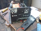 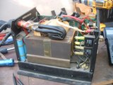 |